|
|

Trajectories reading, interpreting and drawing
Imitation of processing
Tools
Workpiece
Trajectories reading, interpreting and drawing
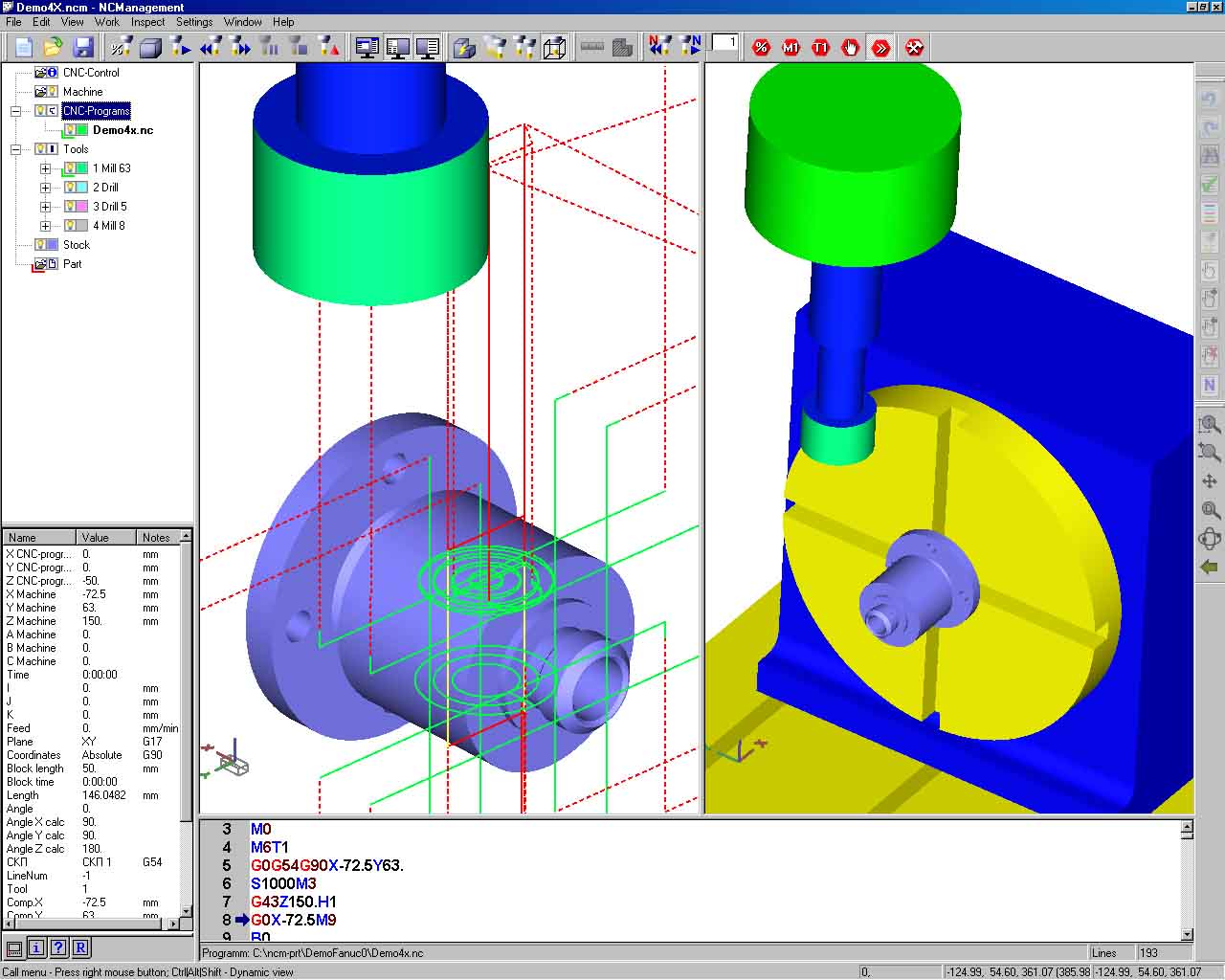 NCM reads the file with CNC program (G–code) and interprets it according
to the CNC model established at the moment. This model is loaded from
the file describing CNC. The read trajectories are displayed in the
graphical window as three-dimensional curves. View management allows
to arbitrarily change the viewpoint, select the scale, set standard
views, etc. Feed and fast motion, cycles and subprograms are highlighted
by the line color and type. Display modes in which compensation is/is
not taken into account are possible. Dynamic bindings allow to accurately
measure the co-ordinates of any point on the trajectory as well as
the distance between points. The textbox displays the program text.
Any changes in the text are immediately displayed in the graphical
window. At that you can view the initial and the edited program simultaneously.
There is an opportunity to change the color of separate sections of
the program text depending on the value of this or that parameter
(the type of compensation, the feedrate, the tool used, etc.). This
opportunity is provided in order to simplify the analysis. Top
NCM reads the file with CNC program (G–code) and interprets it according
to the CNC model established at the moment. This model is loaded from
the file describing CNC. The read trajectories are displayed in the
graphical window as three-dimensional curves. View management allows
to arbitrarily change the viewpoint, select the scale, set standard
views, etc. Feed and fast motion, cycles and subprograms are highlighted
by the line color and type. Display modes in which compensation is/is
not taken into account are possible. Dynamic bindings allow to accurately
measure the co-ordinates of any point on the trajectory as well as
the distance between points. The textbox displays the program text.
Any changes in the text are immediately displayed in the graphical
window. At that you can view the initial and the edited program simultaneously.
There is an opportunity to change the color of separate sections of
the program text depending on the value of this or that parameter
(the type of compensation, the feedrate, the tool used, etc.). This
opportunity is provided in order to simplify the analysis. Top
Imitation of processing
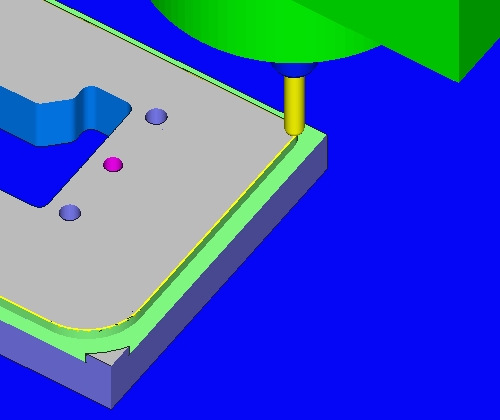 While imitating the processing NCM displays the tool movements and
the current values of working parameters (co-ordinates, feedrate,
cooling, etc.), and calculates the time of processing. There is an
opportunity to move arbitrarily within the program either forward
or backward as well as to execute the program automatically either
step by step or from/till the selected block. NCM displays the removal
procedure of workpiece material while processing according to the
set program, i.e. from any point you can see in dynamics the way the
form of a workpiece changes. The sections where the tool collides
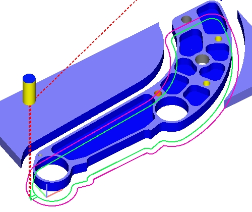
with the surface in fast motion are highlighted by color. The co-ordinates
of every point on either processed or unprocessed surface as well
as (for the processed surface only) the number of the initial program
block executing which this point was obtained are displayed at any
stage. There is also an opportunity to plot an arbitrary section of
a workpiece being processed. The user can imitate the work either
of all the loaded programs or of any program taken separately, or
of any other program segment. Top
While imitating the processing NCM displays the tool movements and
the current values of working parameters (co-ordinates, feedrate,
cooling, etc.), and calculates the time of processing. There is an
opportunity to move arbitrarily within the program either forward
or backward as well as to execute the program automatically either
step by step or from/till the selected block. NCM displays the removal
procedure of workpiece material while processing according to the
set program, i.e. from any point you can see in dynamics the way the
form of a workpiece changes. The sections where the tool collides
with the surface in fast motion are highlighted by color. The co-ordinates
of every point on either processed or unprocessed surface as well
as (for the processed surface only) the number of the initial program
block executing which this point was obtained are displayed at any
stage. There is also an opportunity to plot an arbitrary section of
a workpiece being processed. The user can imitate the work either
of all the loaded programs or of any program taken separately, or
of any other program segment. Top
Tools
NCM allows to set tool parameters directly or to import them from the CAM-system.
In the first case you should indicate for every tool its geometrical size and position it must be placed in.
In the course of processing imitation a tool can be displayed as a wire-frame or half-tone image, or as a conventional marker. You can set the tool color and the degree of tool transparency. Top
Workpiece
NCM provides an opportunity to set the workpiece form and size directly
or to import these data from the CAD/CAM system.You can set a
cylindric workpiece or a workpiece in the form of a plate
(rectangular parallelepiped) directly, i.e. “within” NCM.
The workpiece size and position regarding the co-ordinate system of a
machine can be indicated manually or calculated automatically by CNC
programs dimensions taking the offset into account. A
workpiece of an arbitrary form can be imported from any CAD or
CAD/CAM system that contains STL interface.
Top
|
|